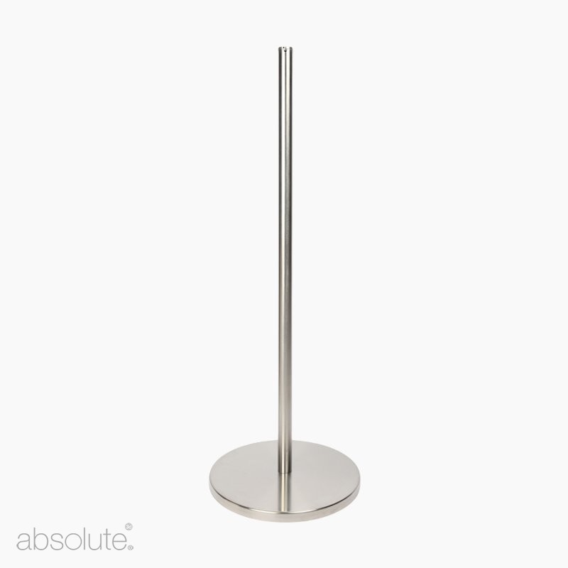


Q Barrier Freestanding
The Freestanding Q Barrier elegantly guides and directs visitors without clashing with the display or decor.
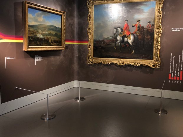
We designed this 'full height' barrier system to guide and control visitors. It is ideally suited to directing the flow of visitors at entrances to exhibits, for ticketing or handling large numbers. It is both a physical and visual message dictating accessibility and ensuring that queuing is an orderly and defined process.
The proportions and detailing have been designed to complement museum, gallery and display environments with clean lines and neutral finishes, although is suited to use in all environments requiring a queueing or visitor guidance solution.
The Q barrier features a wide stable base plate, straight post and tamper proof cap which supports our discreet elastic cord that replaces those dreadful droopy ropes. Simple, effective and ideally suited for flexible layouts.
There is also a range of signage options that will attach easily and securely to the barrier to assist with informing and directing visitors.
Key Features of the Freestanding Q Barrier Stanchion:
- Neutral, clean lines that blend with the environment
- Stable base with non-skid/scratch pads
- Flexible, easy to reconfigure design
- Elasticated cord that gently tugs and effectively guides
- Easy to assemble
- Modular components to accommodate informative signage, using a Q Barrier signage adaptor
|
|
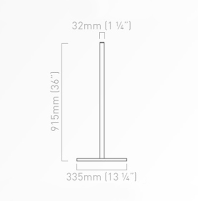
Type: Stanchion Barrier Material & Finish: Stainless steel Dimensions: 915mm high x 335mm diameter base Tear Sheet: View UK Installation Instructions PDF: Click here to download USA Installation Instructions PDF: Click here to download
|
> Read our expert guide: Choosing Art Barriers for Traditional, Transitional and Contemporary Spaces - Click here to read
We recommend up to 2.5 metres as the ideal spacing between barriers, but this can be adjusted slightly to suit individual layouts.
For the best finish it is important to ensure that the cord maintains a level straight line between barriers.
For more permanent installations, please see our Surface Mounted or Floor Socket Q Barrier.
Included:
- 1 x Upright with stainless steel top cap
- 1 x Base Weight
- 1 x Stainless Steel Cover Plate
- 1 x Allen key
Not included/You may also require:
Product Reviews

General Reviews
Museum grade products, designed for all settings. We design and manufacture high quality products in the UK to display, protect and explain artworks as well as to guide and inform visitors. Absolute has built a reputation for innovative, high-specification solutions for museums and galleries around the world, which are available for use in all types of environments, from attractions and hospitality venues to airports, restaurants and everything in between. For more information about how our product solutions could support or enhance your space, please contact us.
Important Note: Due to current high demand, orders for large quantities of barriers or signage products may require an additional 24 hours for despatch. If your order is urgent, please contact us.
Every effort is made to despatch the same day for orders placed before 13:00 (Monday-Thursday, 11:00 Friday), this is subject to warehouse capacity and stock availability. We use UPS courier service; all prices are calculated on weight at the checkout and are delivered by the courier between 8am – 6pm. Please contact us if your delivery country is unavailable for website ordering, this will be shown during checkout. Also note that international orders delivery time does not include customs clearance. Further information about delivery please contact us.
View our full delivery and returns information.
You may also need these


")
")


RELATED ARTICLES
Be inspired, guided, and supported by our latest articles

Why High-Quality Museum Equipment is the Sustainable Choice
The gap between cost increases vs income is ever increasing in the museum sector. Discover why high-quality museum equipment is the sustainable and cost-effective choice in challenging economic times.

A Guide to Museum Barriers: Protecting Exhibits & Visitor Experience
"Every gallery or museum around the world can tell you one terrible moment where through accident, and not through intention, someone got too close, someone tripped, someone fell, and someone bumped into things." Susan Klein - Director of Marketing, Fine
Barrier Care, Installation and Maintenance Tips
It is in the finer details where the over-all finished quality of an art installation or exhibition space can either be enhanced, or undermined. Learn from our top barrier care, installation and maintenance tips.
You may also like
")
")
")
")


")
")

